As already announced in the last article, I am expanding the spectrum of this blog to include topics from (3D) game art. This article on “best practices” for UV unwrapping is the first. This is not intended to be a complete tutorial on UV unwrapping, but assumes that you already have basic experience with it and have mastered your 3D modeling software to the extent that you can implement the tips.
For those who are only interested in the rules, I have put them right at the beginning:
The best practices in detail
For all those who don’t want to simply believe everything I say, or are generally interested in the reasons, I’ll continue here. The all-encompassing reason for these rules is that the aim is to avoid errors in texture baking, especially normal baking.
Every hard edge must be a UV cut, soft edges can be a UV cut.
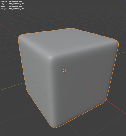
High poly cube for normal baking
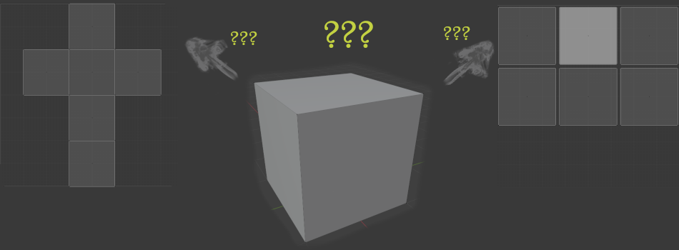
Every hard edge must be a UV cut, otherwise artifacts will occur during normal baking. Conversely, this rule does not apply, even though in hard-surface modeling every UV cut is usually also a hard edge. Let’s imagine that we have a high-poly cube with beautifully rounded edges, as shown here. We now want to transfer these rounded edges to a simple standard cube (8 vertices, 12 edges, 6 faces) using normal baking.
To test the thesis, I have prepared two standard cubes, each with different UV layouts. The first UV layout consists of just a single UV shell and could be familiar to anyone from math class. The second layout, on the other hand, represents the other extreme and uses a single UV shell for each surface and thus follows the rule discussed here, as each edge of the cube is a hard edge.
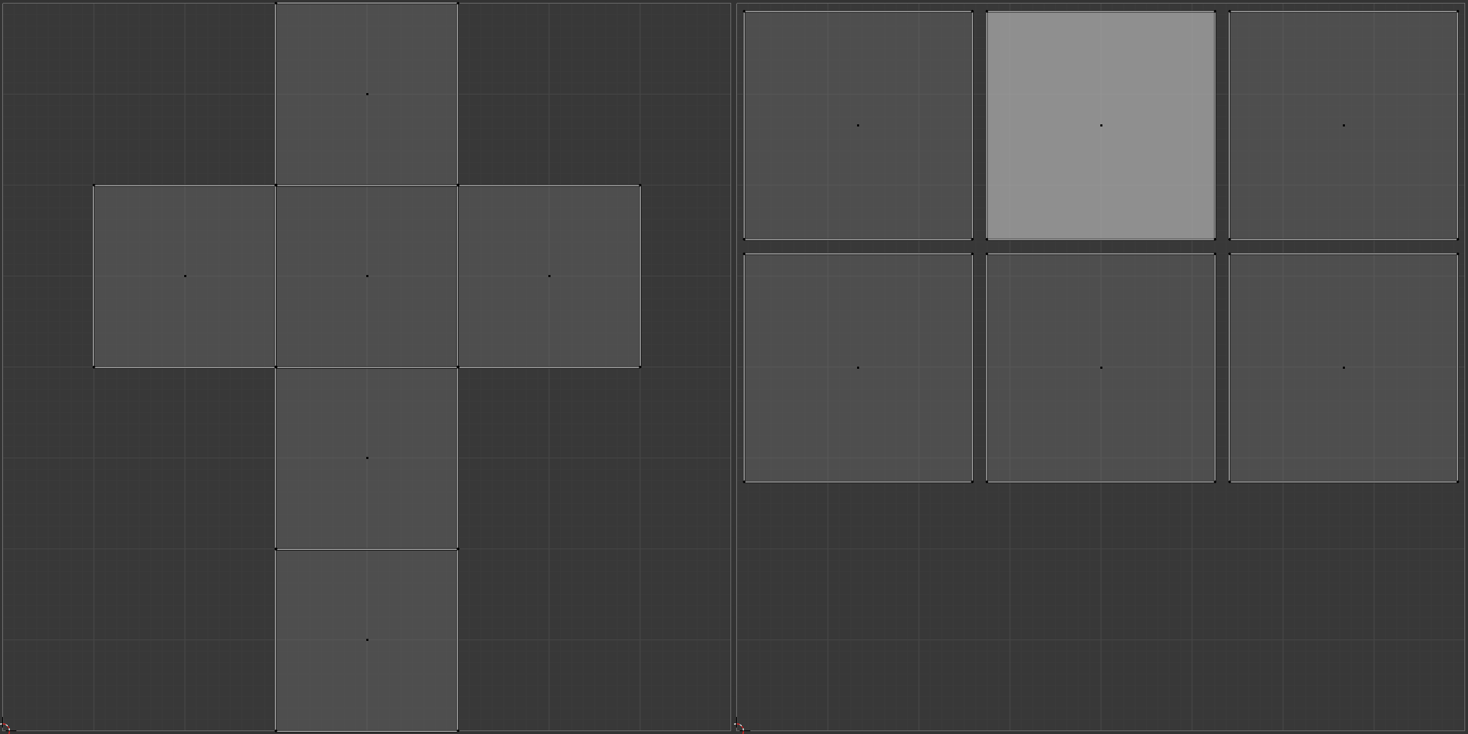
2 UV layouts for a simple cube (left: 1 UV shell, no padding; right: 6 UV shells, with padding)
I then used the different UV layouts to transfer the normals of the high-poly cube with the identical settings. As you can see in the following picture, there are overlays at the edges in the left UV layout, while everything looks fine in the right UV layout. As a small side effect of the right UV layout, a higher texel density can also be used there.
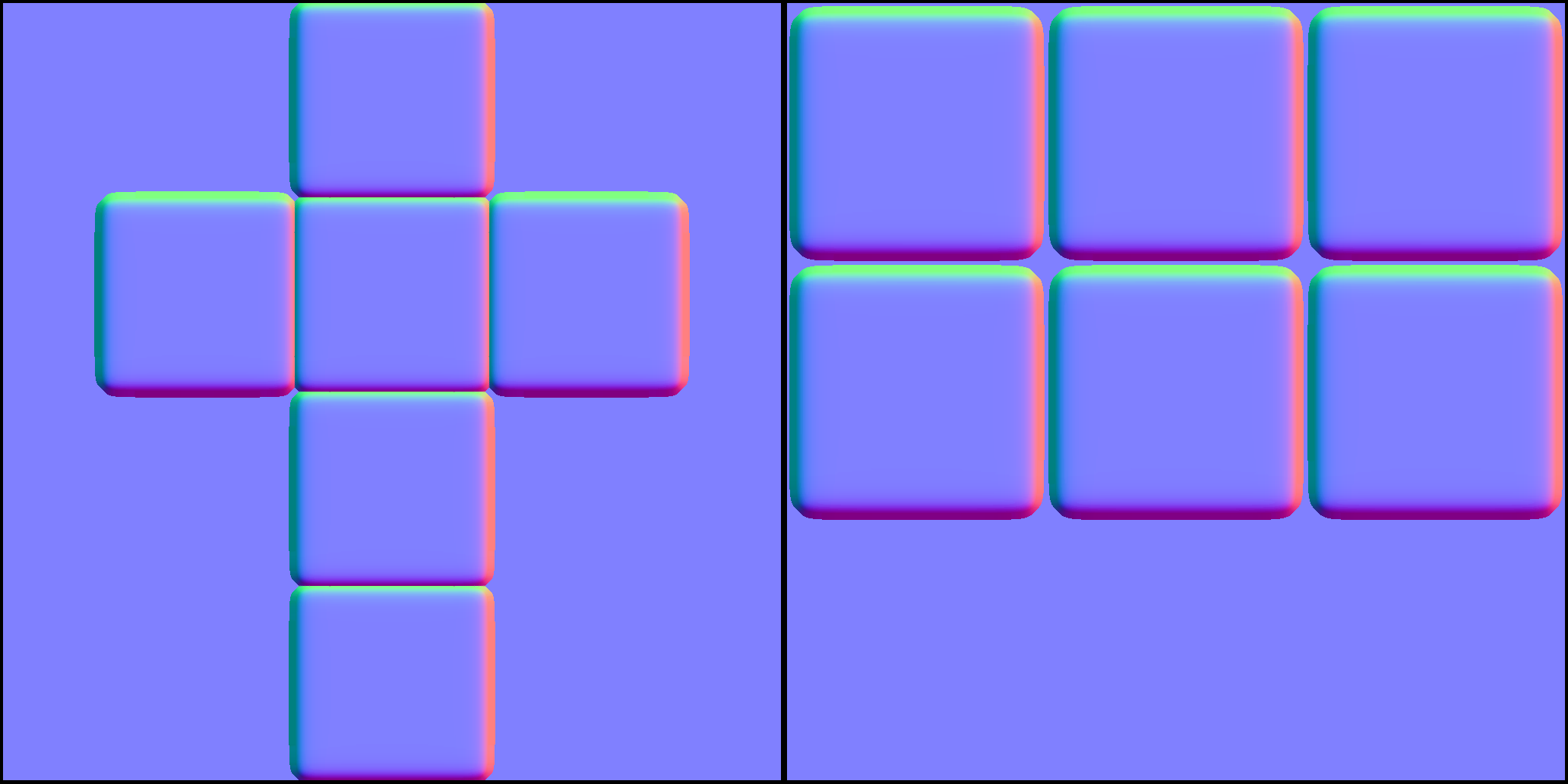
Normal baking results for differen UV layouts (left: 1 UV shell, no padding; right: 6 UV shells, with padding)
The outer edges of the individual UV shells should ideally be perfectly straight.
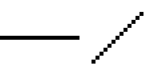
left: straight line; right: line rotated by 45º (no Antialiasing)
Everyone has probably stumbled across the term edge smoothing (anti-aliasing) in the graphics settings of computer games and then there are often obscure abbreviations such as MSAA, FXAA, TAA, … and then there are sometimes multipliers (x4, x16, …). These are techniques designed to compensate for the limitations of our screens. Current monitors (LCD / (O)LED) are pixel-based, which simply means that a pixel is the smallest possible addressable unit for us or the game engine. We can only ever assign a color to a whole pixel and not just half a pixel or even less. If we now have an edge that runs from left to right across the screen, we see a perfect edge, as the pixels are all directly next to each other and thus enable a perfect transition. If we rotate this edge by 45º, for example, we can see clear artifacts of the staircase effect, as shown in the adjacent image.
To prevent such artifacts, it is essential to have perfectly straight outer edges and slight distortions within the UV shells are also accepted, as the artifacts caused by aliasing are often more noticeable than slight distortions within the UV shells. It should be noted that such artifacts are more noticeable the lower the texture resolution is. Even if no problems are visible in the beauty shot for your own portfolio with 4k textures, this does not mean that no artifacts will occur in a “game ready” version with a 1k texture, for example.
The shells should always be aligned with the axes (U or V) and only rotated in 90º increments.
The same reasoning applies here as in the previous point. If the UV shells are aligned with the axes and have perfectly straight outer edges, the outer edges are still perfectly straight and no aliasing / staircase effect can occur. The same applies to rotations in 90º steps.
Ensure a uniform texel density.
Scene with variations in texel density
A uniform texel density is essential in order to achieve a uniform level of detail in texturing at all points of the model. Texture density refers to the number of pixels per unit length (usually px/cm) and of course refers to a specific texture size, e.g. 2k. When determining the current texel density or setting a specific texel density, there are tools for common 3D modeling software that are either directly integrated (e.g. in Maya) or can be added via a plugin (e.g. in Blender).
To summarize: The higher the texel density, the higher the level of detail that can be achieved, but also the higher the necessary memory consumption. Therefore, you always have to weigh up what is the best compromise for the overall result, if you are allowed to decide at all. It is essential that the entire game has as uniform a texel density as possible. You can find out more about this topic at Beyond Extend - Deepdive Texel density.
Ensure that the padding is sufficiently large.
When arranging the various UV shells, always ensure that there is sufficient space between the UV shells. The reason for this is that without sufficient padding, problems can occur in the following areas:
- Normal baking
- Some of you may have heard the term “dilation” in connection with normal baking. This usually allows you to configure by how many px the UV shell of an object may be exceeded. In most cases, the outermost pixels of the normals are simply copied to the outside. It is used to prevent possible rendering errors due to scaling, for example (see MipMaps). Without sufficient padding, the normals of different shells would then overwrite each other.
- MipMap generation
- MipMaps are texture maps in which a texture is available in different resolutions and is saved in a file. MipMaps are important as they can otherwise lead to misrepresentations, e.g. the Moiré pattern, when fine-resolution patterns, e.g. stripes, are viewed from a distance. To prevent this, textures are saved in different resolutions so that the rendering engine can use the “ideal” resolution for the display depending on the displayed size of the 3D model.
Nowadays, MipMaps are usually generated automatically by the game engines, but if you want to get the last bit of quality out of them, you can also create or edit them manually with the appropriate programs. It should be noted that, for example, a 512px wide texture must be created from a 2048px wide texture, i.e. 4px are combined to 1px, which can lead to data from different UV shells being offset against each other without sufficient padding.
Sufficient is a relative term, as it depends on the targeted texture size. The PolyCount Wiki specifies the following minimum values for padding:
| Texture size (px) | Padding (px) |
|---|---|
| 256x256 | 2 |
| 512x512 | 4 |
| 1024x1024 | 8 |
| 2048x2048 | 16 |
The golden rules
And finally, once again the golden rules of UV unwrapping: